Circuit Protection Devices
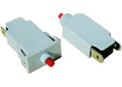
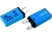
Protection of circuits and products against overload, overheating, and transient conditions becomes more important considering safety aspects and the sensitive nature of many IC components. Selecting and fitting appropriate protection devices can avoid unnecessary service calls and protect sensitive components.
We offer components to suit a variety of applications. These products are generally approved to the relevant safety standards. See the PDF data sheets for more information.
Manual Reset Devices
NP Series
NP Series circuit breakers are small size, single pole overload circuit protectors. They use a spring action and bimetal element to sense a current overload. The bimetal element responds to an overload by opening the electrical contacts. It remains open until the reset button is pushed, thereby closing the electrical contacts and reenergizing the circuit.
NPN type without mounting bush, (PCB mount).
NPS type with 5/16 x 32 threaded bush.
Applications
All kinds of electrical and electronic equipment where overload protection is needed and reset by the user is required. e.g. small appliance, motorized equipment, low power heating equipment, speakers.
Technical Data
- Current rating: 0.3 A to 12 A,, (resistive and inductive load).
- Max voltage rating: AC 250 V, DC 28 V.
- Insulation resistance: >100 MW, (DC 500 V).
- Typical life at rated current: >10000 operations.
- Shock: 30 G (11ms), to IEC 68-2-27, test Ea.
- Vibration: 8 G (57 to 500 Hz/ ± 0.61mm, 10 to 57 Hz), to IEC 68-2-6 test Fc.
- Corrosion: 96 hours at 5% salt spray, to IEC 68-2-11, test Ka.
- Humidity: 240 hours at 95% RH to IEC 68-2-3, test Ca.
- Weight: approximately 2.8 g.
See the PDF datasheet for more technical details: NP series 0.3 A to 12 A![]()
| Type NPN or NPS | Rated Hold AC at 25°C (A) | Max (V) | Trip Time 200% Current | Trip Time 300% Current | Internal Resistance (Ω) Under | Max. Interrupt Current (A) |
|---|---|---|---|---|---|---|
| NP-3 | 0.3 | 250 | 15 sec | 4 sec | 0.8 | 4 |
| NP-4 | 0.4 | 250 | 15 sec | 4 sec | 0.8 | 4 |
| NP-5 | 0.5 | 250 | 15 sec | 4 sec | 0.75 | 6 |
| NP-6 | 0.6 | 250 | 15 sec | 4 sec | 0.75 | 6 |
| NP-7 | 0.7 | 250 | 15 sec | 4 sec | 0.6 | 10 |
| NP-8 | 0.85 | 250 | 15 sec | 4 sec | 0.6 | 10 |
NP-10 |
1.0 | 250 | 15 sec | 4 sec | 0.15 | 20 |
| NP-12 | 1.25 | 250 | 15 sec | 4 sec | 0.15 | 20 |
| NP-14 | 1.4 | 250 | 15 sec | 4 sec | 0.15 | 20 |
| NP-15 | 1.5 | 250 | 15 sec | 4 sec | 0.15 | 30 |
| NP-16 | 1.6 | 250 | 15 sec | 4 sec | 0.12 | 30 |
| NP-17 | 1.75 | 250 | 15 sec | 4 sec | 0.12 | 30 |
| NP-19 | 1.9 | 250 | 15 sec | 4 sec | 0.12 | 30 |
| NP-20 | 2.0 | 250 | 15 sec | 4 sec | 0.12 | 30 |
| NP-22 | 2.2 | 250 | 15 sec | 4 sec | 0.1 | 30 |
| NP-25 | 2.5 | 250 | 15 sec | 4 sec | 0.1 | 30 |
| NP-27 | 2.7 | 250 | 15 sec | 4 sec | 0.08 | 30 |
| NP-30 | 3.0 | 250 | 15 sec | 4 sec | 0.08 | 30 |
| NP-40 | 4.0 | 250 | 15 sec | 4 sec | 0.06 | 40 |
| NP-50 | 5.0 | 250 | 15 sec | 4 sec | 0.06 | 50 |
| NP-60 | 6.0 | 250 | 15 sec | 4 sec | 0.06 | 60 |
| NP-70 | 7.0 | 250 | 15 sec | 4 sec | 0.04 | 70 |
| NP-80 | 8.0 | 250 | 15 sec | 4 sec | 0.04 | 80 |
| NP-90 | 9.0 | 250 | 15 sec | 4 sec | 0.04 | 90 |
| NP-100 | 10.0 | 250 | 15 sec | 4 sec | 0.02 | 100 |
NP-120 |
12.0 | 250 | 15 sec | 4 sec | 0.02 | 120 |
A-0709 Series
Mounting options - with nut (U type), snap-in (W type).
Applications
Power supply, amplifier, UPS, regulator, generator.
Specification
- Rating: 4 - 16 Amperes in 1 A steps, (13 models).
- Input power: 32 VDC / 120 VAC / 240 VAC.
- Dielectric strength: 1500 VAC / 1 min.
- Interrupt capacity 1000 A @ 120 VAC, 200 A@ 240 VAC.
- Calibration:
@ 25°C 105% of rated current - continuous.
@ 25°C 196% to 134% of rated current - may / may not trip.
@ 25°C 200% of rated current - trip within 1 minute.
e.g. 4 amp model @ 25°C 150% of rated current - trip within 60 mins. - Contact endurance: @ 120VAC / 150% of rated current - 500 cycles.
See the PDF datasheet for more technical details: A-0709 series 4 A to 16 A![]()
BS Series

Applications
Motors, power strips, machine tools, UPS, office equipment, power supplies.
Features
- Single or double pole ON/OFF rocker switch with protection device in a single component to avoid overload current or short circuit.
- Switch automatically returns to OFF position on overload.
- Trip free mechanism.
- Fault reminder.
- Snap-in panel mounting.
Technical Data
- Current rating: 0.3 A to 20 A, (resistive and inductive load).
- Max voltage rating: AC 250 V, DC 28 V.
- Insulation resistance: >100 MW, (DC 500 V).
- Typical life at rated current: >10000 operations.
- Minimum contact gap: 2.5 mm.
- Shock: 30 G (11ms), to IEC 68-2-27, test Ea.
- Vibration: 8 G (57 to 500 Hz/ ± 0.61 mm, 10 to 57 Hz), to IEC 68-2-6 test Fc.
- Corrosion: 96 hours at 5% salt spray, to IEC 68-2-11, test Ka.
- Humidity: 240 hours at 95% RH to IEC 68-2-3, test Ca.
- Weight: approximately 10.6 g
Other versions
- Versions with LED or neon illumination.
- Short terminals (6.6mm long).
- Round profile rocker.
- Double pole version with overload, short circuit and earth leakage protection.
- Magnetic factors of 4x and 7x rating.
- Double pole with thermal magnetic x7 device.
See the PDF datasheet for more technical details: BS series 0.3 A to 20 A![]()
Auto Reset Devices
AN Series

These compact overcurrent protectors are designed to protect audio speaker systems, amplifiers and power supplies from internal overcurrents. They are available up to 12 amps.
Features
- High current accuracy *.
- Protection against excessive temperature.
- Snap action.
- Automatic reset type.
- Long life.
- PBT resin enclosure.
- Economically priced.
- Reliable.
- Two mounting options.
* Low current models should be used within following maximum ambient temperatures:
- AN-04: 50°C
- AN-05: 50°C
- AN-06: 60°C
- AN-08: 70°C
Note: Rated hold current decreases with temperature >25°C, and increases with temperature <25°C.
See the PDF datasheet for more technical details: AN series 0.4 A to 12 A![]()
| Type 1: PC | Type 2: Tags | Rated Hold AC Current at 25°C (A) | Maximum Voltage (V) | Trip Time 200% Current | Trip Time 300% Current | Internal Resistance (mΩ) Under | Maximum Interrupt Current (A) |
|---|---|---|---|---|---|---|---|
| AN-041 | - | 0.4 | 250 | < 30 sec | < 5 sec | < 700 | 4 |
| AN-051 | - | 0.5 | 250 | < 30 sec | < 5 sec | < 600 | 5 |
| AN-061 | - | 0.6 | 250 | < 30 sec | < 5 sec | < 500 | 6 |
| AN-081 | - | 0.85 | 250 | < 30 sec | < 5 sec | < 500 | 10 |
| AN-101 | AN-102 | 1.0 | 250 | < 30 sec | < 5 sec | < 150 | 20 |
| AN-121 | AN-122 | 1.25 | 250 | < 30 sec | < 5 sec | < 150 | 20 |
| AN-141 | AN-142 | 1.4 | 250 | < 30 sec | < 5 sec | < 100 | 20 |
| AN-161 | AN-162 | 1.6 | 250 | < 30 sec | < 5 sec | < 100 | 20 |
| AN-171 | AN-172 | 1.75 | 250 | < 30 sec | < 5 sec | < 100 | 20 |
| AN-191 | AN-192 | 1.9 | 250 | < 30 sec | < 5 sec | < 75 | 20 |
| AN-221 | AN-222 | 2.2 | 250 | < 30 sec | < 5 sec | < 75 | 20 |
| AN-251 | AN-252 | 2.5 | 250 | < 30 sec | < 5 sec | < 75 | 25 |
| AN-271 | AN-272 | 2.7 | 250 | < 30 sec | < 5 sec | < 75 | 25 |
| AN-301 | AN-302 | 3.0 | 250 | < 30 sec | < 5 sec | < 35 | 30 |
| AN-401 | AN-402 | 4.0 | 250 | < 30 sec | < 5 sec | < 35 | 40 |
AN-501 |
AN-502 | 5.0 | 250 | < 30 sec | < 5 sec | < 30 | 50 |
| AN-601 | AN-602 | 6.0 | 250 | < 30 sec | < 5 sec | < 30 | 60 |
| AN-701 | AN-702 | 7.0 | 250 | < 30 sec | < 5 sec | < 30 | 60 |
AN-801 |
AN-802 | 8.0 | 250 | < 30 sec | < 5 sec | < 30 | 60 |
| AN-901 | AN-802 | 9.0 | 250 | < 30 sec | < 5 sec | < 30 | 60 |
| AN-1001 | AN-1002 | 10.0 | 250 | < 30 sec | < 5 sec | < 30 | 60 |
| AN-1201 | AN-1202 | 12.0 | 250 | < 30 sec | < 5 sec | < 30 | 60 |
TS/1 Thermostats

Supplied with two silicon wires and fully enclosed in a shrink sleeve, (case is live). Order by TS/1 (temperature rating).
Applications
Battery Pack, small domestic appliances, transformer, lighting ballast.
Features
- Rated: (resistive load)
24 VDC 100 mA. 50K+ cycles
120 VAC 10A. 10K+ cycles
120 VAC 6A. 30K+ cycles
240 VAC 6A. 10K+ cycles - Temperature: 12 versions.
- Operating tolerance: Standard ±5°C.
- Reset differential: 10° to 40°.
- Contacts: Current carrying normally closed. Snap action, quick make / break.
- Interrupt capacity: 120 VAC - 60A. 5 cycles.
- Overshoot temperature: 200°C / 3 minutes.
- Dielectric strength: 1500 VAC / minute.
- Ballast rated: 10,000 cycles.
- Weight: 5 grams (with wires).
- ISO 9002
| Part Number | Rated Temperature °C | UL Approval E 125871(S) |
|---|---|---|
| FC 672701 | 45 | √ |
| FC 672702 | 60 | √ |
| FC 672703 | 70 | √ |
| FC 672704 | 80 | √ |
| FC 672705 | 85 | √ |
| FC 672706 | 90 | √ |
| FC 672707 | 95 | √ |
| FC 672708 | 100 | √ |
| FC 672709 | 110 | √ |
| FC 672710 | 120 | √ |
| FC 672711 | 130 | |
| FC 672712 | 140 |

The PDF datasheet has the technical details: TS/1 Thermostats 45° to 140°![]()
One Shot Devices
Thermal Cutouts

Applications
Cliff thermal cutouts are available with axial and radial leads. They are widely used to prevent overheating of electrical components like motors, transformers and solenoids. They are particularly used to keep the electronic circuits from over heating in equipment such as computers, VTRs, inverters, switching power supplies and medical equipment.
Structure
Tin / Lead plated soft copper wire leads are welded to a fusible alloy with a specific melting point. Special resins coat the alloy in order to prevent surface oxidation and to ensure complete cutoff function at melting point. The fusible alloy is completely insulated within the case by sealing the leads and the case with a special resin compound.
Working Theory
When the ambient temperature of the thermal cutout rises, the fusible alloy melts. The electrical circuit in the thermal cutout is opened. Two separate spheres form at the edges of the leads through surface tension of the melting fusible alloy. Additional insulation between the spheres is provided by the coating resin which encapsulates the surface.
Features
Available in two types - axial and radial.
Highly reliable due to their outstanding thermal sensitivity.
Cliff thermal cutouts are approved by various international standards including JEAML (DENAN), UL, CSA, VDE and BEAB.
![]()
See the PDF datasheet for more technical details: Thermal Cutouts 1 A to 7 A![]()
Definitions of the characteristics
- Nominal Functioning Temperature or Nominal Operating Temperature under the JEAML. Under such standards as UL, CSA and VDE which basically comply with the IEC specifications, it is called Rated Functioning Temperature. According to the JEAML, thermal cutouts, when conducting the detection current and subject to the increasing rate of temperature designated by the specifications, must function in the tolerance range of ±7°C to the rated functioning temperature. With the IEC specifications, they must function in the range of +0°C~-10°C to the rated functioning temperature.
- Operating Temperature of a thermal cutout carrying current less than 0.1A, and placed in an oil bath where the temperature rises 1°C per minute.
- Holding Temperature is the maximum temperature at which a thermal cutout can be maintained without operating while conducting the rated current for a period of time specified by the manufacturer.
- Maximum Temperature Limit is the maximum temperature at which mechanical and electrical properties of a thermal cutout can be maintained without resuming conductivity after operating.
- Approved=√. Pending=°.
H type, rated 2 A, 250 VAC. Simple plug-in holder for mounting H type thermal cutouts. No insulation tube is required, (labour saving in the transformer line). Material is PBT. Available only while stocks last.
| Model | Nominal Operating Temp. °C | Operating Temp. °C | Holding Temp. °C | Maximum Temp. °C | Current (A) | Volt (V) | JEAML | UL E73591 | CSA LR60621 | VDE 13710-1171-0007 | BEAB C0532 |
|---|---|---|---|---|---|---|---|---|---|---|---|
| H 076 | 76 | 73 ±2.5 | 50 | 85 | 2 | 250 | 33-793 | √ | √ | ° | ° |
| H 086 | 86 | 81 ±2 | 60 | 95 | 2 | 250 | 33-792 | √ | √ | ° | √ |
| H 100 | 103 | 98 ±2 | 70 | 180 | 2 | 250 | 33-696 | √ | √ | √ | √ |
| H 110 | 117 | 112 ±2 | 85 | 180 | 2 | 250 | 33-696 | √ | √ | √ | √ |
| H 125 | 127 | 124 ±2 | 95 | 180 | 2 | 250 | 33-411 | √ | √ | √ | √ |
| H 130 | 136 | 130 ±2 | 105 | 180 | 2 | 250 | 33-411 | √ | √ | √ | √ |
| H 135 | 140 | 135 ±2 | 105 | 180 | 2 | 250 | 33-411 | √ | √ | √ | √ |
| H 145 | 150 | 145 ±2 | 115 | 180 | 2 | 250 | 33-412 | √ | √ | √ | √ |
| H 169 | 169 | 165 ±2 | 130 | 180 | 2 | 250 | 33-706 | √ | √ | √ | √ |
H-A type, rated 2 A, 250 VAC.
| Model | Nominal Operating Temp. °C | Operating Temp. °C | Holding Temp. °C | Maximum Temp. °C | Current (A) | Volt (V) | JEAML | UL E73591 | CSA LR60621 | VDE 13710-1171-0007 | BEAB C0532 |
|---|---|---|---|---|---|---|---|---|---|---|---|
| H 100A | 103 | 98 ±2 | 70 | 180 | 2 | 250 | 33-696 | √ | √ | √ | √ |
| H 110A | 117 | 112 ±2 | 85 | 180 | 2 | 250 | 33-696 | √ | √ | √ | √ |
| H 125A | 127 | 124 ±2 | 95 | 180 | 2 | 250 | 33-411 | √ | √ | √ | √ |
| H 130A | 136 | 130 ±2 | 105 | 180 | 2 | 250 | 33-411 | √ | √ | √ | √ |
| H 135A | 140 | 135 ±2 | 105 | 180 | 2 | 250 | 33-411 | √ | √ | √ | √ |
| H 145A | 150 | 145 ±2 | 115 | 180 | 2 | 250 | 33-412 | √ | √ | √ | √ |
E type, rated 3 A, 250 VAC and 5 A, 125 VAC.
| Model | Nominal Operating Temp. °C | Operating Temp. °C | Holding Temp. °C | Maximum Temp. °C | Current (A) | Volt (V) | JEAML | UL E73591 | CSA LR60621 | VDE 13710-4510-1010/0010 | BEAB 0790 |
|---|---|---|---|---|---|---|---|---|---|---|---|
| E 0 | 76 | 73 ±2.5 | 50 | 85 | 3 | 250 | 33-793 | ° | ° | ° | ° |
| E 1 | 86 | 81 ±2 | 60 | 95 | 3 | 250 | 33-792 | ° | ° | ° | ° |
| E 2 | 103 | 98 ±2 | 70 | 180 | 3 | 250 | 33-696 | √ | √ | √ | √ |
| E 3 | 117 | 112 ±2 | 85 | 180 | 3 | 250 | 33-696 | √ | √ | √ | √ |
| 5 | 125 | - | √ | √ | - | - | |||||
| E 4 | 127 | 124 ±2 | 95 | 180 | 3 | 250 | 33-411 | √ | √ | √ | √ |
| 5 | 125 | - | √ | √ | - | - | |||||
| E 5 | 136 | 130 ±2 | 105 | 180 | 3 | 250 | 33-411 | √ | √ | √ | √ |
| 5 | 125 | - | √ | √ | - | - | |||||
| E 7 | 150 | 145 ±2 | 115 | 180 | 3 | 250 | 33-412 | √ | √ | √ | √ |
| 5 | 125 | - | √ | √ | - | - | |||||
| E 8 | 169 | 165 ±2 | 130 | 180 | 3 | 250 | 33-706 | √ | √ | √ | √ |
| 5 | 125 | - | - | - | - | - |
K type, rated 1 A, 250 VAC and 3 A, 50 VAC (except K10).
| Model | Nominal Operating Temp. °C | Operating Temp. °C | Holding Temp. °C | Maximum Temp. °C | Current (A) | Volt (V) | JEAML | UL | CSA LR60621 | VDE | BEAB C0849 |
|---|---|---|---|---|---|---|---|---|---|---|---|
| K 10 | 102 | 98 ±2 | 70 | 160 | 0.5 | 250 | 33-696 | ° | √ | ° | √ |
| 2.5 | DC50V | - | ° | √ | ° | √ | |||||
| K 11 | 115 | 112 ±2 | 95 | 160 | 1.0 | 250 | 33-696 | ° | √ | ° | ° |
| 3.0 | DC50V | - | ° | √ | ° | ° | |||||
| K 12 | 130 | 126 ±2 | 100 | 160 | 1.0 | 250 | 33-411 | ° | √ | ° | ° |
| 3.0 | DC50V | - | ° | √ | ° | ° | |||||
| K 13 | 133 | 130 ±2 | 100 | 160 | 1.0 | 250 | 33-411 | ° | √ | ° | √ |
| 3.0 | DC50V | - | ° | √ | ° | ° | |||||
| K 14 | 150 | 145 ±2 | 120 | 160 | 0.5 | 250 | 33-412 | ° | √ | ° | √ |
| 3.0 | DC50V | - | ° | √ | ° | √ | |||||
| K 16 | 169 | 165 ±3 | 130 | 180 | 1.0 | 250 | 33-706 | - | - | - | - |
| 3.0 | DC50V | - | - | - | - | - | |||||
| K 18 | 187 | 183 ±3 | 160 | 260 | 1.0 | 250 | 33-844 | - | - | - | - |
| 3.0 | DC50V | - | - | - | - | - |
V type, rated 2 A, 250 VAC.
| Model | Nominal Operating Temp. °C | Operating Temp. °C | Holding Temp. °C | Maximum Temp. °C | Current (A) | Volt (V) | JEAML | UL E73591 | CSA LR60621 | VDE 13710-4510-0006/1008 | BEAB 0807 |
|---|---|---|---|---|---|---|---|---|---|---|---|
| V 076 | 76 | 73 ±2.5 | 50 | 85 | 2 | 250 | 33-793 | √ | √ | √ | √ |
| V 086 | 86 | 81 ±2 | 60 | 95 | 2 | 250 | 33-792 | √ | √ | √ | √ |
| V 100 | 103 | 98 ±2 | 70 | 160 | 2 | 250 | 33-696 | √ | √ | √ | √ |
| V 110 | 117 | 112 ±2 | 95 | 160 | 2 | 250 | 33-696 | √ | √ | √ | √ |
| V 125 | 131 | 126 ±2 | 95 | 160 | 2 | 250 | 33-411 | √ | √ | √ | ° |
| V 130 | 135 | 131 ±2 | 100 | 160 | 2 | 250 | 33-411 | √ | √ | √ | ° |
| V 145 | 150 | 145 ±2 | 115 | 160 | 2 | 250 | 33-412 | √ | √ | √ | √ |
| V 169 | 169 | 165 ±2 | 130 | 180 | 2 | 250 | 33-706 | ° | √ | √ | √ |
| V 187 | 187 | 183 ±2 | 160 | 200 | 2 | 250 | 33-844 | ° | √ | √ | √ |
VS type, rated 1 A, 250 VAC and 3 A, 50 VDC.
| Model | Nominal Operating Temp. °C | Operating Temp. °C | Holding Temp. °C | Maximum Temp. °C | Current (A) | Volt (V) | JEAML | UL E73591 | CSA LR60621 | VDE 13710-1171-0002 | BEAB 0569 |
|---|---|---|---|---|---|---|---|---|---|---|---|
| VS 07 | 76 | 73 ±2.5 | 50 | 85 | 1.0 | 250 | 33-793 | √ | √ | ° | √ |
| VS 08 | 86 | 81 ±2 | 60 | 95 | 1.0 | 250 | 33-792 | √ | √ | ° | √ |
| 2.5 | DC50V | - | √ | √ | ° | ° | |||||
| VS 10 | 103 | 98 ±2 | 70 | 160 | 1.0 | 250 | 33-696 | √ | √ | √ | √ |
| 3.0 | DC50V | - | √ | √ | ° | √ | |||||
| VS 11 | 117 | 112 ±2 | 95 | 160 | 1.0 | 250 | 33-696 | √ | √ | √ | √ |
| 3.0 | DC50V | - | √ | √ | ° | √ | |||||
| VS 12 | 128 | 124 ±2 | 100 | 160 | 1.0 | 250 | 33-411 | √ | √ | √ | √ |
| 3.0 | DC50V | - | √ | √ | ° | ° | |||||
| VS 13 | 136 | 131 ±2 | 100 | 160 | 1.0 | 250 | 33-411 | √ | √ | √ | √ |
| 3.0 | DC50V | - | √ | √ | ° | ° | |||||
| VS 14 | 150 | 145 ±2 | 115 | 160 | 1.0 | 250 | 33-412 | √ | √ | √ | √ |
| 3.0 | DC50V | - | √ | √ | ° | √ | |||||
| VS 16 | 169 | 165 ±2 | 130 | 180 | 1.0 | 250 | 33-706 | √ | √ | - | √ |
| 3.0 | DC50V | - | - | - | - | - | |||||
| VS 18 | 187 | 183 ±2 | 160 | 200 | 1.0 | 250 | 33-844 | - | - | - | - |
| 3.0 | DC50V | - | - | - | - | - |
Y type, rated 3 A, 250 VAC and 5 A, 50 VDC.
| Model | Nominal Operating Temp. °C | Operating Temp. °C | Holding Temp. °C | Maximum Temp. °C | Current (A) | Volt (V) | JEAML | UL | CSA LR60621 | VDE 13710-4510-0011 | BEAB 0791 |
|---|---|---|---|---|---|---|---|---|---|---|---|
| Y 2 | 103 | 98 ±2 | 70 | 180 | 3 | 250 | 33-696 | ° | √ | √ | √ |
| 4 | 125 | - | - | - | - | - | |||||
| Y 3 | 117 | 112 ±2 | 95 | 180 | 3 | 250 | 33-696 | ° | √ | √ | √ |
| 5 | 125 | - | ° | √ | - | - | |||||
| Y 4 | 128 | 124 ±2 | 100 | 180 | 3 | 250 | 33-411 | ° | √ | √ | √ |
| 5 | 125 | - | ° | √ | - | - | |||||
| Y 5 | 136 | 131 ±2 | 100 | 180 | 3 | 250 | 33-411 | ° | √ | √ | √ |
| 5 | 125 | - | ° | √ | - | - | |||||
| Y 7 | 150 | 145 ±2 | 115 | 180 | 3 | 250 | 33-412 | ° | √ | √ | √ |
| 5 | 125 | - | ° | √ | - | - | |||||
| Y 8 | 169 | 165 ±3 | 130 | 180 | 3 | 250 | 33-706 | ° | √ | √ | √ |
| 5 | 125 | - | - | - | - | - | |||||
| Y 9 | 187 | 183 ±3 | 160 | 200 | 3 | 250 | 33-844 | - | - | - | - |
| 5 | 125 | - | - | - | - | - |
L type, rated 5 A, 250 VAC and 7 A, 50 VDC.
| Model | Nominal Operating Temp. °C | Operating Temp. °C | Holding Temp. °C | Maximum Temp. °C | Current (A) | Volt (V) | JEAML | UL | CSA LR60621 | VDE | BEAB |
|---|---|---|---|---|---|---|---|---|---|---|---|
| L 2 | 102 | 98 ±2 | 70 | 160 | 5 | 250 | 33-696 | ° | √ | ° | ° |
| 7 | 125 | - | ° | √ | - | - | |||||
| L 3 | 115 | 112 ±2 | 95 | 160 | 5 | 250 | 33-696 | ° | √ | ° | ° |
| 7 | 125 | - | ° | √ | - | - | |||||
| L 4 | 130 | 126 ±2 | 100 | 160 | 5 | 250 | 33-411 | ° | √ | ° | ° |
| 7 | 125 | - | ° | √ | - | - | |||||
| L 5 | 133 | 130 ±2 | 100 | 160 | 5 | 250 | 33-411 | ° | √ | ° | ° |
| 7 | 125 | - | ° | √ | - | - | |||||
| L 7 | 150 | 145 ±2 | 120 | 160 | 5 | 250 | 33-412 | ° | √ | ° | ° |
| 7 | 125 | - | ° | √ | - | - | |||||
| L 8 | 169 | 165 ±3 | 130 | 180 | 5 | 250 | 33-706 | ° | ° | ° | ° |
| 7 | 125 | - | ° | ° | - | - | |||||
| L 9 | 187 | 183 ±3 | 130 | 200 | 5 | 250 | 33-844 | - | - | - | - |
| 7 | 125 | - | - | - | - | - |
P type, rated 2 A, 250 VAC and 3.5 A, 50 VDC.
| Model | Nominal Operating Temp. °C | Operating Temp. °C | Holding Temp. °C | Maximum Temp. °C | Current (A) | Volt (V) | JEAML | UL E73591 | CSA LR60621 | VDE 13710-1171-0002 | BEAB 0569 |
|---|---|---|---|---|---|---|---|---|---|---|---|
| P 07 | 76 | 73 ±2.5 | 50 | 85 | 1 | 250 | 33-793 | ° | ° | ° | ° |
| P 08 | 86 | 81 ±2 | 65 | 95 | 1 | 250 | 33-792 | ° | ° | ° | ° |
| P 10 | 103 | 98 ±2 | 70 | 160 | 1 | 250 | 33-696 | √ | √ | √ | √ |
| 2.5 | DC50 | - | √ | √ | ° | ° | |||||
| P 11 | 117 | 112 ±2 | 95 | 160 | 1 | 250 | 33-696 | √ | √ | √ | √ |
| 2.5 | DC50 | - | √ | √ | ° | ° | |||||
| P 12 | 128 | 124 ±2 | 100 | 160 | 1 | 250 | 33-411 | √ | √ | √ | √ |
| 3 | DC50 | - | √ | √ | ° | ° | |||||
| P 13 | 136 | 131 ±2 | 100 | 160 | 1 | 250 | 33-411 | √ | √ | √ | √ |
| 3 | DC50 | - | √ | √ | ° | ° | |||||
| P 14 | 150 | 145 ±2 | 115 | 160 | 1 | 250 | 33-412 | √ | √ | √ | √ |
| 3 | DC50 | - | √ | √ | ° | √ |
N type, rated 1 A, 250 VAC and 3 A, 50 VDC.
| Model | Nominal Operating Temp. °C | Operating Temp. °C | Holding Temp. °C | Maximum Temp. °C | Current (A) | Volt (V) | JEAML | UL E73591 | CSA LR60621 | VDE 13710-4510-1009/0009 | BEAB 0617 |
|---|---|---|---|---|---|---|---|---|---|---|---|
| N 0 | 76 | 73 ±2.5 | 50 | 85 | 1.0 | 250 | 33-793 | ° | √ | ° | √ |
| 2.5 | DC50 | - | √ | √ | ° | √ | |||||
| N 1 | 86 | 81 ±2 | 60 | 95 | 1.0 | 250 | 33-792 | √ | √ | ° | √ |
| 2.5 | DC50 | - | √ | √ | ° | √ | |||||
| N 2 | 103 | 98 ±2 | 70 | 180 | 1.0 | 250 | 33-696 | √ | √ | √ | √ |
| 3.0 | DC50 | - | √ | √ | ° | √ | |||||
| N 3 | 117 | 112 ±2 | 85 | 180 | 1.0 | 250 | 33-696 | √ | √ | √ | √ |
| 3.0 | DC50 | - | √ | √ | ° | √ | |||||
| N 4 | 127 | 124 ±2 | 95 | 180 | 1.0 | 250 | 33-411 | √ | √ | √ | √ |
| 3.0 | DC50 | - | √ | √ | ° | √ | |||||
| N 5 | 136 | 130 ±2 | 105 | 180 | 1.0 | 250 | 33-411 | √ | √ | √ | √ |
| 3.0 | DC50 | - | √ | √ | ° | √ | |||||
| N 6 | 140 | 135 ±2 | 105 | 180 | 1.0 | 250 | 33-411 | √ | √ | √ | √ |
| 3.0 | DC50 | - | √ | √ | ° | √ | |||||
| N 7 | 150 | 145 ±2 | 115 | 180 | 1.0 | 250 | 33-412 | √ | √ | √ | √ |
| 3.0 | DC50 | - | √ | √ | ° | √ | |||||
| N 8 | 169 | 165 ±3 | 130 | 180 | 1.0 | 250 | 33-706 | √ | √ | √ | √ |
| 3.0 | DC50 | - | - | - | - | - |
EP type, rated 3 A, 250 VAC and 4 A, 50 VDC.
| Model | Nominal Operating Temp. °C | Operating Temp. °C | Holding Temp. °C | Maximum Temp. °C | Current (A) | Volt (V) | JEAML | UL E73591 | CSA | VDE | BEAB |
|---|---|---|---|---|---|---|---|---|---|---|---|
| EP 0 | 76 | 73 ±2.5 | 50 | 85 | 3.0 | 250 | 33-793 | ° | ° | ° | ° |
| EP 1 | 86 | 81 ±2 | 60 | 95 | 3.0 | 250 | 33-792 | ° | ° | ° | ° |
| EP 2 | 103 | 98 ±2 | 70 | 180 | 3.0 | 250 | 33-696 | √ | ° | ° | ° |
| 3.5 | 125 | - | - | - | - | - | |||||
| EP 3 | 117 | 112 ±2 | 85 | 180 | 3.0 | 250 | 33-696 | √ | ° | ° | ° |
| 4.0 | 125 | - | √ | ° | - | - | |||||
| EP 4 | 127 | 124 ±2 | 95 | 180 | 3.0 | 250 | 33-411 | √ | ° | ° | ° |
| 4.0 | 125 | - | √ | ° | - | - | |||||
| EP 5 | 136 | 130 ±2 | 105 | 180 | 3.0 | 250 | 33-411 | √ | ° | ° | ° |
| 4.0 | 125 | - | √ | ° | - | - | |||||
| EP 7 | 150 | 145 ±2 | 115 | 180 | 3.0 | 250 | 33-412 | √ | ° | ° | ° |
| 4.0 | 125 | - | √ | ° | - | - |
Please contact CLIFF sales for more information.
Our site uses PDF (portable document format) files to store information on our products. To view these files you should have a PDF reader installed. You can download Adobe Reader for free.